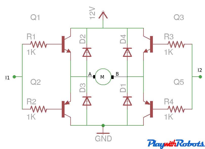
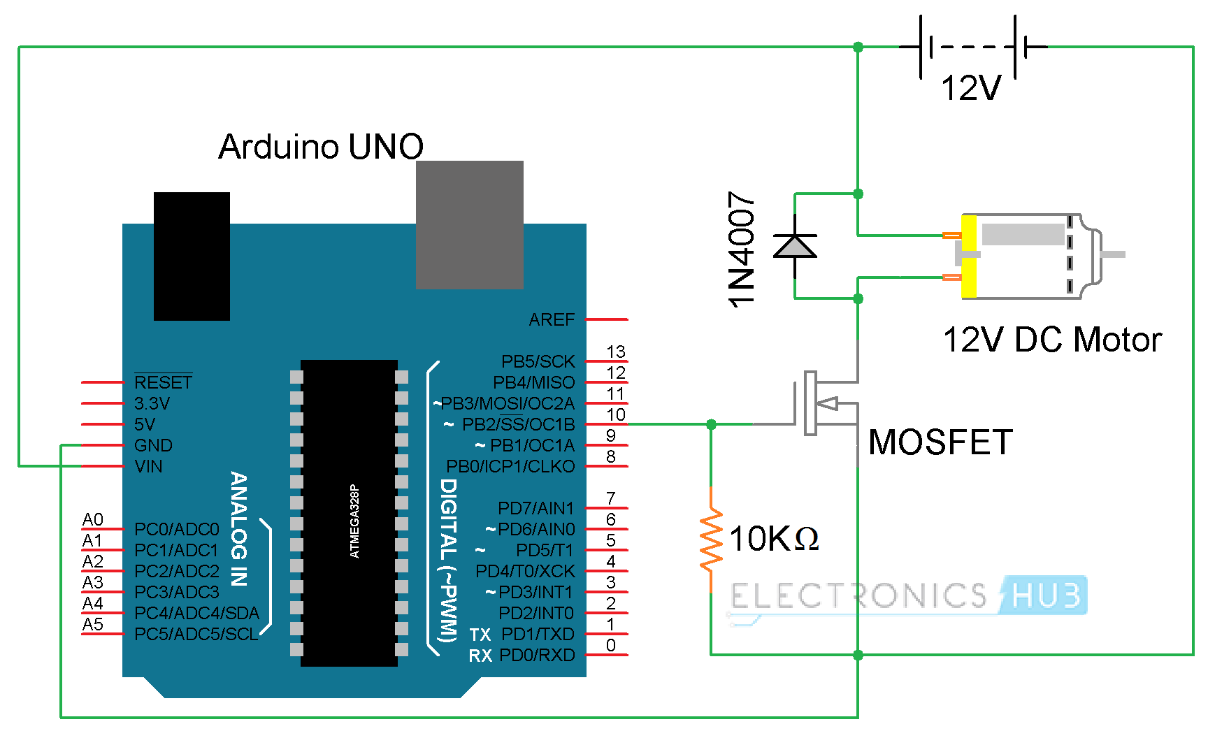
This drive can control a Brushed DC motor in one direction. This drive is often used in safety critical applications because a short circuit cannot turn the motor on. V+ M MOSFET Driver. • AN893 – “Low-cost Bidirectional Brushed DC Motor Control Using the PIC16F684”. No power switches are needed for this circuit, just two push buttons and in Potentiometer to control the direction and speed of DC Motor. One push button will rotate motor clockwise and other will rotate it counter clockwise. One n-channel MOSFET is required to control speed of motor. Relays are used to switch the directions of Motor. The speed of dc motor can be controller in many ways like we can add a variable resistor in series with the motor but we will control the speed of dc motor using the l298 motor controller by the PWM (pulse width modulation) method which is efficient than the other methods. This the simplest way to control the speed of a 'normal' DC motor. The MOSFET is configured as a source follower. The output voltage is gate voltage minus threshold voltage. Four quadrant dc motor direction control, direction controller of dc motor using tranistor, speed control of dc motor using pwm technique and h bridge, Abstracts: DC Motor speed control is carried out by use of Four Quadrant Chopper drive.
im building a circuit atm that drive a dc motor (24V, 5Amp) in both direction.(Not using H-bridge because of the high amp motor, I cant find anything at the local store at least).For now the circuit look likes this:

Which when the Arduino set pin 7 and 8 to HI-LOW, motor got 1 direction. And when LOW-HI is the opposite.(Relay switch the negative and positive connections)
However with this method I cant control the speed of the motor. I would love to make the motor slowly increase it speed.
I'm thinking to use a MOSFET and connect it to the PWM pin on the Arduino this method only works for 1 direction but not when reverse.
I'm lost, can someone point me a direction or giving me some link to go to. Thanks you first in advance.
3 Answers
$begingroup$First make a unidirectional PWM speed controller, like this:-
simulate this circuit – Schematic created using CircuitLab
M1 is a 'logic level' FET rated to turn fully on with 5V on the Gate and easily handle the applied voltage and current. R1 keeps M1 turned off if the Arduino's PWM output is floating or disconnected. Lm and Rm represent the internal inductance and resistance of the motor.
D1 is a fast switching Schottky diode which prevents high voltage spikes (caused by magnetic energy stored in the motor's inductance) that would otherwise destroy the FET. It also improves efficiency by recirculating current through the motor while the magnetic field is collapsing.
To change direction you just have to reverse the motor leads like you did before. The relay contacts must be wired between the speed controller and the motor, like this:-
The motor goes forward when one relay is operated, and reverse when the other relay is operated. When both relays are released the motor has a short across it, so it will stop quickly and resist being rotated mechanically.

Before switching directions you should stop the motor by slowly ramping the PWM down to zero and then releasing both relays. Otherwise it will draw a very high current as it reverses, because while still spinning in the original direction it generates a voltage which adds to the applied voltage.
Bruce AbbottBruce Abbott $begingroup$
You can't control speed directly with the relays, because they are mechanical and you can't switch them in high-speed. You pretty much have two solutions: use an H-bridge or use the relays to switch direction and a single transistor to control speed.
There are H-bridges that control a 24V, 5A motor. You usually can't find them on a local store. If local store components are a requirement, you have the option of building your own H-bridge with discrete components. The harder part will usually be the high-side, since your Arduino is at most 0-5V and your motor is 24V, and P-MOSFETs are harder to find in bigger amps, but you can usually work it out with optocouplers. By the way, you usually want to isolate with optocouplers anyway. Also remember to properly calculate the driving requirements, because the Arduino may not handle the gate current capacitances. The bottom-most circuit in this thread looks like a nice starting point.
Since you already have the relay switches working, it may be easier to go for the second option. For that, the simplest way is to use an N-channel MOSFET between the relays 'ground' and the actual ground. Don't forget to properly calculate the driving requirements too. Since you didn't provide actual schematics, it's hard to give better advice, but the schematic from this page looks good (reproduced for completeness):
You can change the DPDT relay for what you already have, and the TIP120 for a more powerful MOSFET.
The mosfet PWM drive and relays should not be a problem if
- your motor changes its direction when the polarity changes; there exist one direction only motors that have no permanent magnets but a magnetizing coil.
- you have carefully thought what happens if you change the direction at full speed
- you have added some spark supressors to make your relays to live longer. A motor this big haves substantial stray inductance that causes sparks in opening relay switches. See the addendum:
- you know that a motor can take many times more current when started compared to a steady run.
Addendum for spark supression:
If one tooks off a DC supply wire from a running motor, a spark is seen. This is common for heavily inductive parts such as relays, motors, electric magnets ets... The spark is caused by induction. In coils that are connected to a DC voltage it means that the coil current never starts or stops in zero time, it happens only gradually.When a DC supply wire is taken off, the current still continues and degrades gradually until all magnetic energy is dissipated. The current chooses that way which breaks most easily. Often it's the air and that we see as a spark.
Suppress the spark by giving an easier way for that inductive spike. Take two more than 12 V zener diodes, say 15 V each. Connect them series, but opposite directions. Connect this dual zener supressor parallel with your motor. It does not short the 12 V supply because 15 V is needed for any current. But your relay gets no welding treatment when the contact opens because the inductive spike current is wasted in a zener diode.
Accepted supplementary note:
Mosfet Motor Driver Circuit
Inductive current limiter can be used too. When the a running motor is suddenly supplied with reverse voltage, the supply current will spike. An inductor at the power source will limit the momentary current spike and this will be less abusive to the power source.
user287001user287001